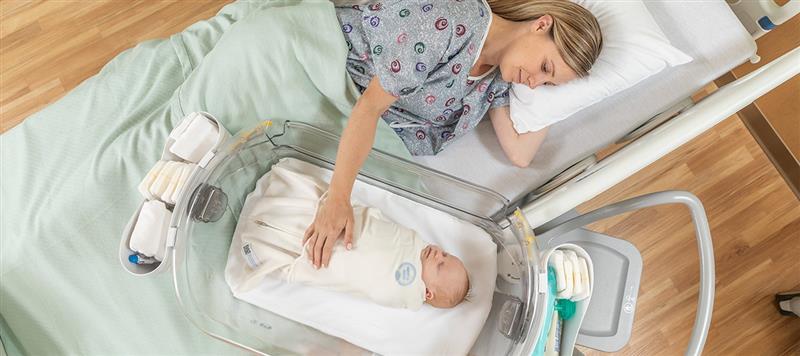
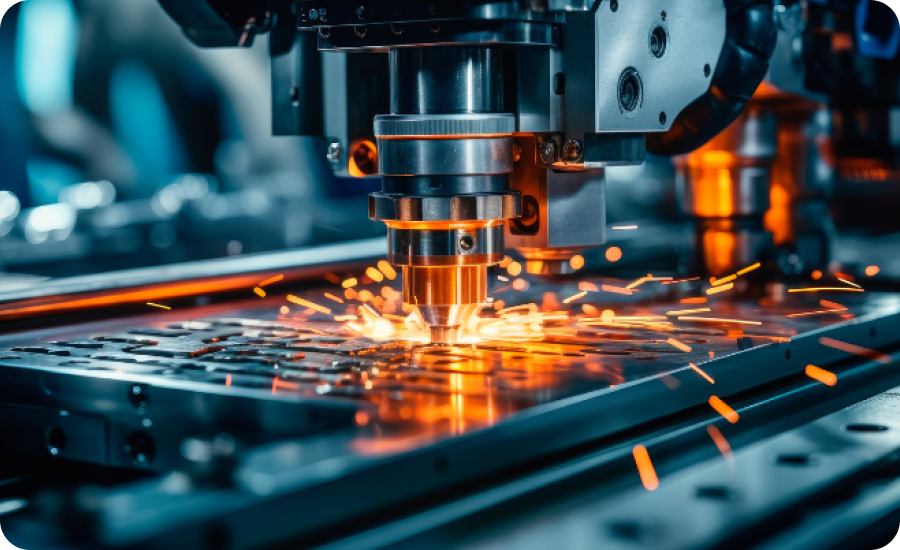
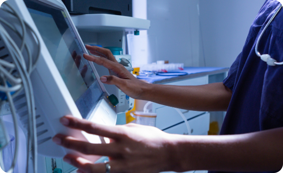
Why we’re different.
MPE Inc. offers a clear, predictable path to commercialization. That means you can focus on the science and technology of your life-transforming capital equipment or device, while we focus on meeting market demands, reducing risk, and adhering to your budget.
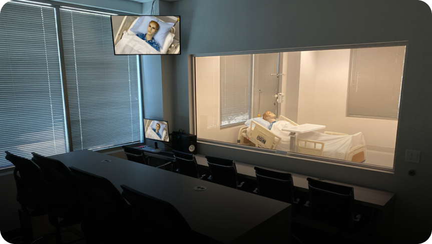
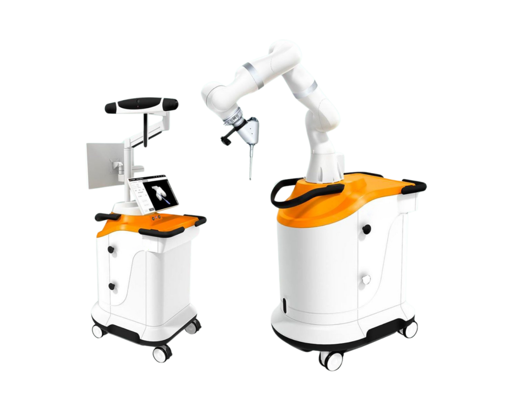
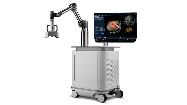
Unified, adaptive, MedTech commercialization platform.
Our commercialization platform employs control planes throughout each step to ensure your medical device product is differentiated, compliant, and easy to adopt. Our unified approach ensures seamless transitions between phases and a consistent focus on growth. We can take over the entire process, or simply take on specific parts, all to ensure a holistic, expertise-driven approach that results in peace of mind for your team.